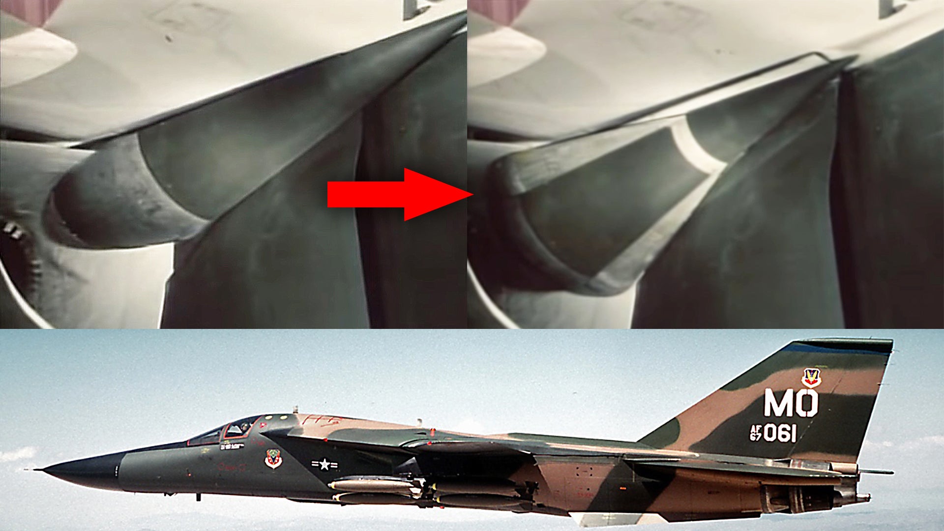
The swing-wing F-111 Aardvark had a very tumultuous genesis, but there was no doubt that it was extremely advanced for its time. It never ended up serving with the Navy, but the Air Force made good use of it for the tactical and strategic strike roles, as well as an electronic warfare platform in the form of the EF-111 Raven. The jet looked like a sharp, hot knife slicing through the air at low-level and high-speed. It certainly was fast, but this high-speed capability came in part from the result of the aircraft’s fascinating variable geometry inlet ‘spike and cone’ design that helped feed massive volumes of stable air into the jet’s troublesome twin Pratt & Whitney TF30 turbofan engines.
The F-111’s spike and cone design almost looks organic it is so beautifully engineered. The complexity of the Aardvark’s inlet configuration is well known. After its initial configuration, it went through two subsequent design iterations, named the Triple Plow I and Triple Plow II, in an attempt to overcome issues with airflow to the TF30s that were becoming notoriously finicky.
You can see the entire video from where the clip of the spike and cone transitioning was taken (at 22:17 runtime) below:

The F-111’s overall intake design works to separate the boundary air layer from the fuselage and lower wings in order to provide stable, high-volumes of air into the engines. The variable geometry spike and cone arrangement is used to keep this boundary layer air out of the intake and keep supersonic air from hitting the engine fan face. You can read all about jet inlet design, which is one of the most challenging aspects of a high-performance aircraft’s design, as well some of the relatively exotic methods engineers have devised to simplify these complex systems and to make them better suited for modern low-observable (stealthy) aircraft, in these past War Zone pieces linked here, here, and here.
In a study about the efficiency of the inlets, NASA describes an early-build F-111A’s inlet functionality as such:
The test airplane had two external compression inlets beneath the wing-fuselage junctures. These inlets were approximately quarter-round segments of axially symmetric inlets, and each provided airflow to one of the engines through separate ducts about 4.11 meters (13.5 feet) long. The inlets incorporated variable geometry to attain inlet-engine airflow matching and to adjust the amount of compression throughout the operating range. Inlet geometry together with the free-stream Mach number and airflow demand of the engines fixed the position of the compression shock system.
…The two-cone air compression surface or “spike,”… devices which were used to prevent low-energy boundary-layer air from entering the inlet…
…
Spike translation was controlled as a function of local Mach number (ahead of the inlet) and diffuser exit Mach number. This portion of the control included position feedback. Second-cone angle was controlled by the same parameters in a loop which maintained a scheduled shock position pressure ratio.
…
At subsonic and low transonic flight speeds, the inlet spike was normally positioned forward and the second cone fully collapsed by the inlet controller to minimize spillage drag and compression. As the aircraft Mach number increased, the spike translated rearward and the second cone expanded according to the preset control system schedule. In this way, increased compression was obtained as the supersonic flow was decelerated by two conical shocks prior to deceleration to subsonic velocities through a normal shock near the cowl lip.
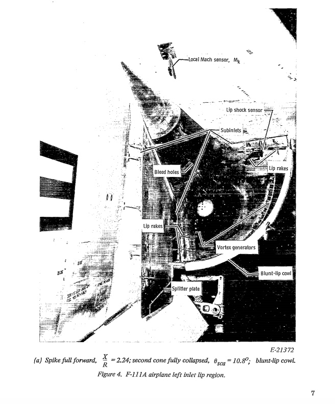
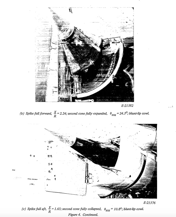
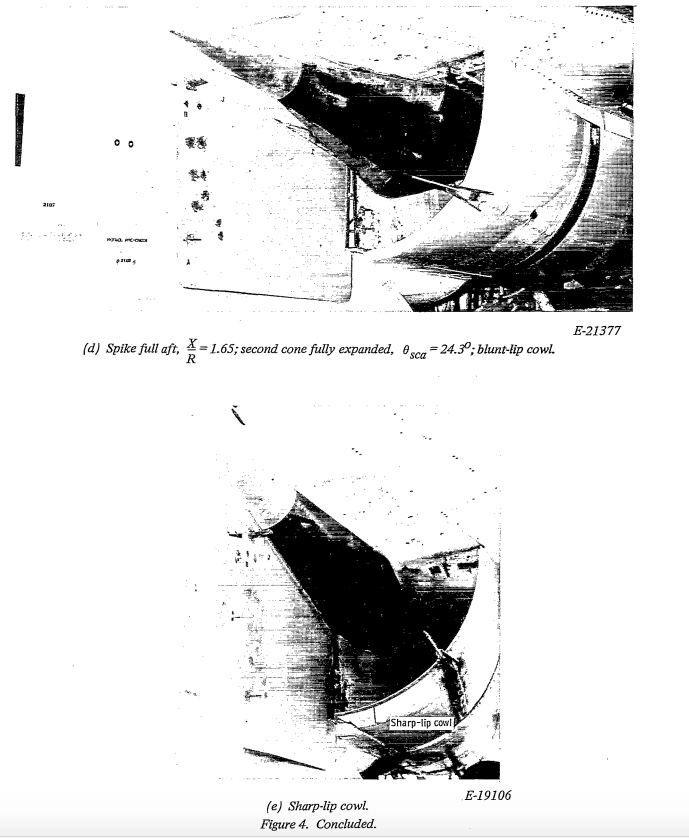
The revised Triple Plow I and II intakes still relied on a similar spike and cone design, but in the case of the Triple Plow II, it was enlarged significantly. Other changes to the inlet design are discussed by F-111.net in some detail:
Operational F/EF-111As, F/RF-111Cs, the first FB-111A (67-0159), and the canceled F-111Ks were fitted with Triple Plow I inlets, which featured hydraulically translated cowls.
The remaining FB-111A/F-111Gs, as well as all F-111D/E/Fs were fitted with Triple Plow II inlets, which featured three ‘blow-in’ doors. This redesign increased the separation between the inlets and fuselage, removed the external splitter panel, and featured inlet spikes 18-inches longer than the Triple Plow I’s. The fuselage of Triple Plow II aircraft angled back ever so slightly at the inlets to create more room between the two structures. These aircraft also featured a small, round inlet between the engine inlet and the fuselage. Finally, the F-111D/E/F and FB-111A all had a pattern of gray, and/or fiberglass-brown panels of radar absorbing material (RAM) on the interior of their inlets.
A couple of “special cases”: The second FB-111A (67-0160) was fitted with Super Plow inlets, which were similar to the Triple Plow II except that the translating cowls were replaced with two ‘blow-in’ doors instead of three. The first five F-111Bs (151xxx) were fitted with essentially Triple Plow I inlets, while the last two (152xxx) had essentially Super Plows. Refer to the Ginter Book on this subject for details.
While the Triple Plow II inlet reportedly increased inlet area by ten percent, it’s unclear if that was precisely true. Measurements of the inlets suggest the TP II may be marginally larger than the TP I, but nothing like ten percent. However, the frontal area of the inlets may have increased by that much because of the shifting of the inlet farther out from the fuselage.
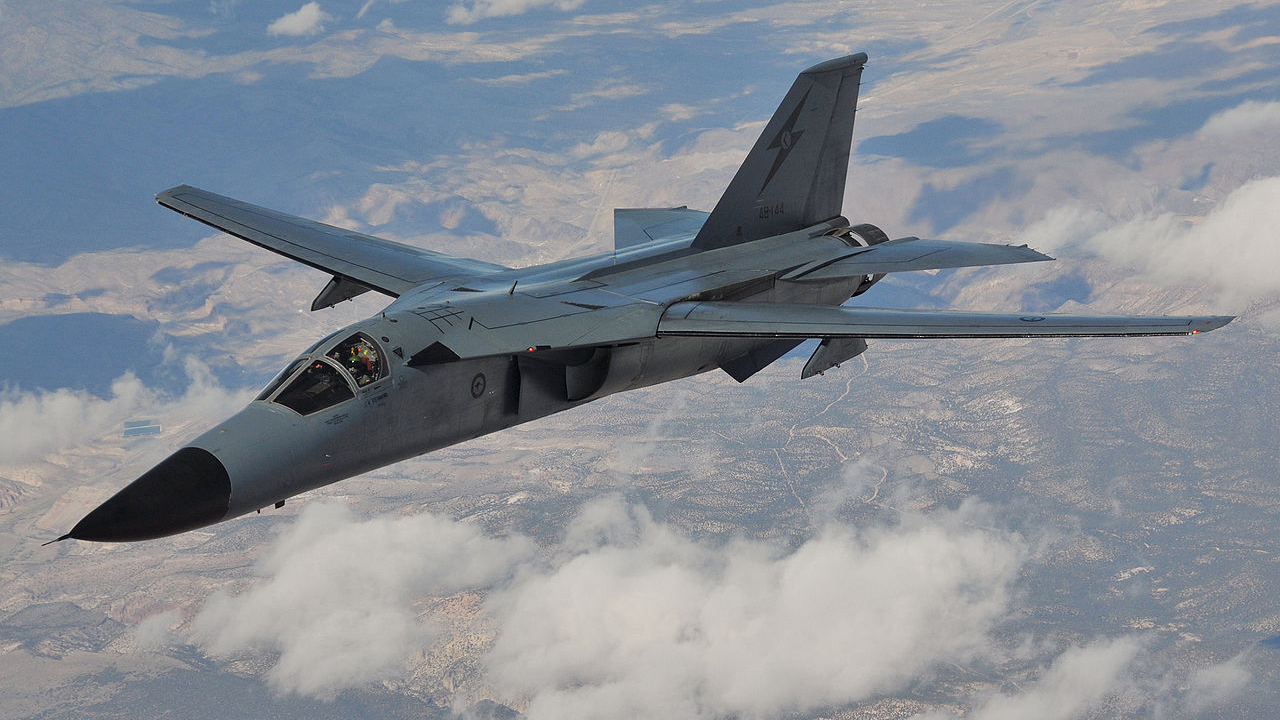
While other swing-wing jets, notably the F-14 Tomcat, get most of the attention, the F-111 was truly an amazing aircraft. Most may remember it best for its precision strike, low-level penetration, and spectacular dump-and-burn capabilities, but its inlet design was definitely another of its truly fascinating features.
If you would like to read about what it was like to fly the F-111 during the Cold War, make sure to read this special feature of ours.
Contact the author: Tyler@thedrive.com
