Even with the almost surreal size of America’s defense budget, most people would be blown away with how many elaborate installations dot the American landscape that are dedicated to the testing and development of new military technologies and weaponry. These include everything from giant sound-stage like buildings used test missile seekers in action, to lakes where new submarine technologies are run through their paces. They also include a number of outdoor radar cross section measurement facilities, commonly known inside the aerospace and defense world as “RCS test ranges.”
From Palm Beach, Florida, to Boardman, Oregon, these ranges are often mistaken for clandestine airstrips or have conspiracy theories related to underground bases or even alien technology slapped on them. But their true role is to carefully evaluate the radar signatures of aircraft designs from different aspects and using different radar bandwidths.
Radar signature test sites date back to the dawn of low observable aircraft design, but as the stealth revolution finally got underway in the late 1970s and early 1980s, they became far more technologically advanced than their predecessors.
Their very mission necessitates a large open space with a flat linear area positioned in line with various radar emitters. A pole, or a number of poles, often designed of acute angles or of a radar transparent substance like foam, are used to raise aircraft models high above the ground for testing. Obviously security is a major concern at many of these installations, as testing means putting potentially very sensitive aircraft designs and shapes high-up in the air. As such, these facilities are often located in very desolate and/or pre-secured areas, and feature elaborate security measures and clearly marked borders.
RCS test facilities also usually feature sliding shelters to hide the test article when not being tested, and large hangar-like buildings for storage, not to mention at least one big array of antennas at the opposite end of facility as the test pylon or pylons. Finally, some do feature underground areas which serve the same function as the moving shelter but in a much more functional manner. Mix all these features together and RCS test facilities can look more like a set from Close Encounter of The Third Kind than a place to where radar measurements are taken on model airplanes.
Of all the radar cross section test facilities (aside from the DYCOMS system at Area 51 and the flying NT-43A RAT bird), one of the most elaborate is Lockheed Martin’s Helendale RCS measurement facility. Conveniently located in the Mojave Desert, just 45 miles east of Lockheed’s Skunk Works headquarters at Plant 42 in Palmdale, California, the installation sits where the old World War II era Helendale Airport once was, on approximately ten square miles of land. In fact, one of the airport’s old runways is still in operation for smaller aircraft, like Lockheed’s company operated PC-12s that ferry personnel to clandestine sites around the American Southwest, and is lit for nighttime operations. But to be clear, that airstrip is anything but public.
The first phase of the modern Helendale range facility was built in the early 1980s—just as stealth technology was beginning to boom. By that time the Skunk Works’ F-117 Nighthawk was already operating in a highly classified manner, flying from deep in the Nevada desert out of Tonopah Test Range Airport and Area 51.
In 1985 the facility saw a major upgrade, which expanded it from a fairly standard two “pit” setup, with the farthest pit being 5,500 feet from the main antenna array, to a three pit layout that measured some 8,200 feet in length. A massive bunker-like concrete installation at the farthest end made up the third and farthest pit, which included a large retractable pole and an underground staging area for lightly modifying, mounting and dismounting test articles. This subterranean hangar like structure is known as the “upper chamber” and is something of a modern marvel in its own right, with its retractable roof and articulating and very stealthy test pole that can be raised high above the pit and retracted far below, deep beneath the upper chamber.
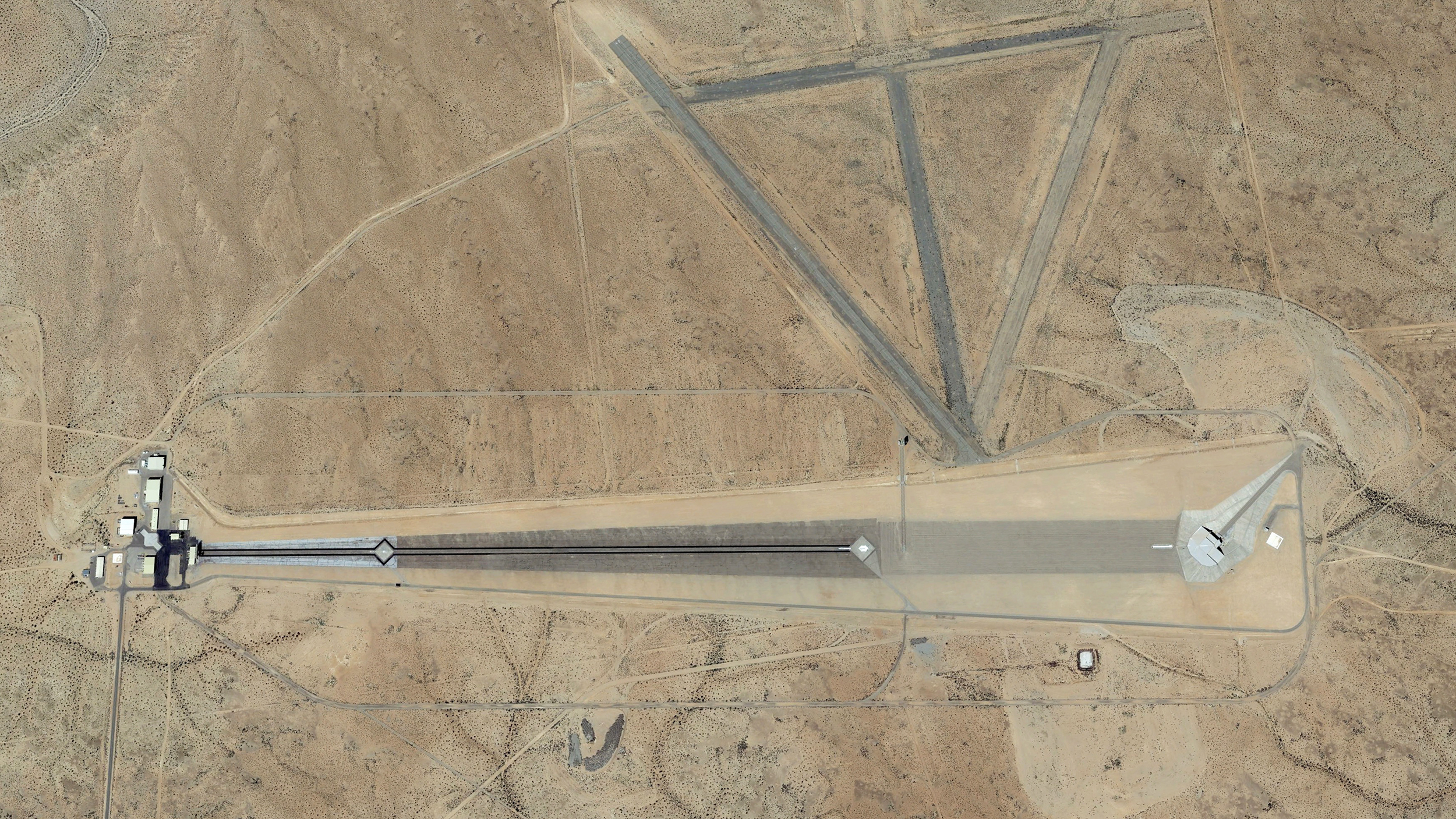
At the other end of the facility, by the main array, a series of hangar, support, and control buildings are present, with the large 70 foot tall dish array sitting at the foot of the perfectly flat concrete slab that continues for roughly 7,500 feet until it terminates at the underground pit. The surface is perfectly smooth, with the natural curvature of the earth negated by design. The facilities various main radar arrays are positioned together, with each being are attached to a hydraulic lift that can position them up or down. Other radar arrays can be placed closer to the poles farther down on the range, and are setup on tracks so that they can be moved in and out of position. Here are some great aerial shots of the facility.
According to the website Otherhand.org, which also has some awesome annotated pictures of the installation, the three pits spaced out along the flat surface are described as such:
“Moving 1,400′ downrange from the Antenna Array, we come to Antenna Pit 1. At this location, test objects can be placed upon four different mounts. The support may be either a 14′ long metal or composite pylon, a foam column, or an inflated air column. The targets mounted at Pit 1 may be up to 14′ in length and weigh up to 1,600 pounds. The targets here are placed upon the mount using either a crane or forklift.
Immediately uprange of Pit 1, visible on the surface of the range, is a long white metal cover. Under this cover is a hinged calibration pylon. Prior to testing a model at Pit 1, the calibration pylon is extended with a known, measured shape mounted on it. The technicians at the operations complex can then adjust and calibrate their equipment on the basis of a known shape. The calibration pylon is then retracted and an actual model measured.
Moving next to a point 5,000′ from the antenna array, we come to Pit 2. This 80′ deep pit is covered by hinged white doors on the surface and contains a pylon extended by means of a hydraulic ram. Just beneath these doors, and above the retracted pylon is a small workroom in which models up to 50′ in length and weighing up to 6,000 pounds may be mounted to the pylon. Immediately adjacent and uprange to Pit 2 is a much smaller pit containing a calibration shape mounted on a hinged pylon. It functions in the same manner as the calibration pit for Pit 1.
This is pretty much the limit of the first phase of the facility at Helendale. But then in 1985, work began to extend the range and the major bells and whistles were put in.
A large 60′ diameter mobile antenna on a crawler-type transporter was added 5,300′ from the main antenna array. When not in use, the transporter moves the large dish antenna laterally, off to the west side of the range. This massive antenna required a specially constructed roadbed and bridge over a flood control channel. The antenna, known as MOBATS, is used for low frequency, high power RF measurements. This mobile crawler antenna seems to be a replacement for an antenna pit planned at the 5,400′ point, but never implemented.
At the 7,300′ mark, we come to a very long white metal cover in the surface of the range. Beneath it is another calibration pit (Area 50), the largest of the range at 130′ long. As with the other calibration pylons, a simple methodology is used to raise it. The pylon is merely hinged at one end, and after the cover doors are opened, it is elevated from its horizontal resting position within a well to a near vertical position. Again in this case, its purpose is to place an object of known shape and size into the radar beam to calibrate the receiving equipment prior to actual model testing.
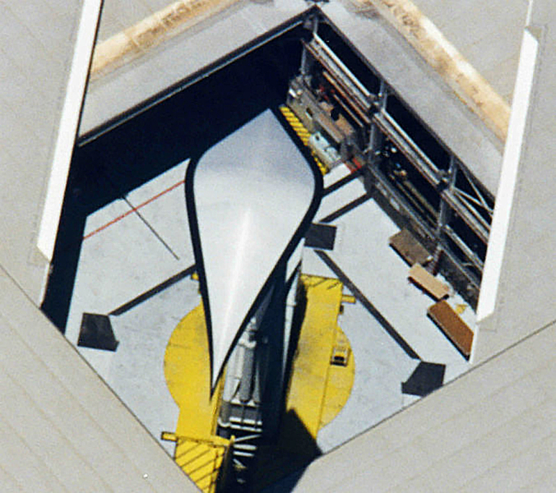
The jewel of the facility is found at the 7,500′ point. This curious structure, in the depression at the far end of the range, is known as the “Upper Chamber” (or Area 30 during construction). Although it appears to be built of solid concrete, it is actually composed of concrete blocks. On the side of the structure with the vertical face, there is a large, side-sliding hangar door in the 40′ high face of the structure. It is through this door that models are brought into the Upper Chamber.
Careful inspection of the Upper Chamber’s roof reveals what appears to be a square cover, 80′ on a side, with a split along a diagonal. This cover retracts on two sides, separating along the diagonal, exposing an 80′ square opening into the Upper Chamber below. When closed, an air bag arrangement seals the diagonal seam.
Surprisingly, the useable area within the Upper Chamber is less than it appears when viewed from outside. Actual level floor space is only about 130′ by 110′, about 14,000 square feet. Most of the area apparently covered in concrete surrounding the Upper Chamber is actually covered slope. At the time of construction this area was not utilized and left as covered, but bare slope.”
The site goes on to describe the interior of the upper chamber space:
“The area within the Upper Chamber is primarily a workroom and staging area. There is a large overhead traveling bridge hoist for the movement and manipulation of RCS models. There is also a diesel generator, a control room, restrooms and a small winch room off to one end. There are no office areas. The right rear portion of the Upper Chamber is dominated by the Silo and its cover.
The Silo, also known as Area 35, is located directly beneath the floor of the Upper Chamber and takes up much of the usable floor space. It is a massive circular shaft with an inside diameter of 33′, reaching a depth of 210′ below the floor of the Upper Chamber. It is constructed of reinforced concrete with a minimum wall thickness of 3-1/2′. The upper walls of the Silo are a bit thicker. Construction of the Silo structure alone required in excess of 3,000 cubic yards of concrete to construct. That’s the contents of about 300 fully loaded cement trucks, hence the local residents’ tales of “cement trucks lined up for miles” during the facility’s construction. The depth of the Silo puts it well below the water table of the adjacent Mojave River, and ensuring seepage water is constantly pumped out is a concern. There are some stories that the design of the Silo was based upon that of an underground Titan missile silo. If true, there was undoubtedly intense interest in the site from Soviet spy satellites during construction!
Residing within the Silo is the retractable pylon upon which models are placed for raising into the radar beams for measurement. The pylon rests upon a counterbalanced hoist structure just beneath it, which is raised by a dual cable winch mechanism. In addition to a ladder, access is provided to various levels of the Silo by means of a small, Swedish made personnel elevator.
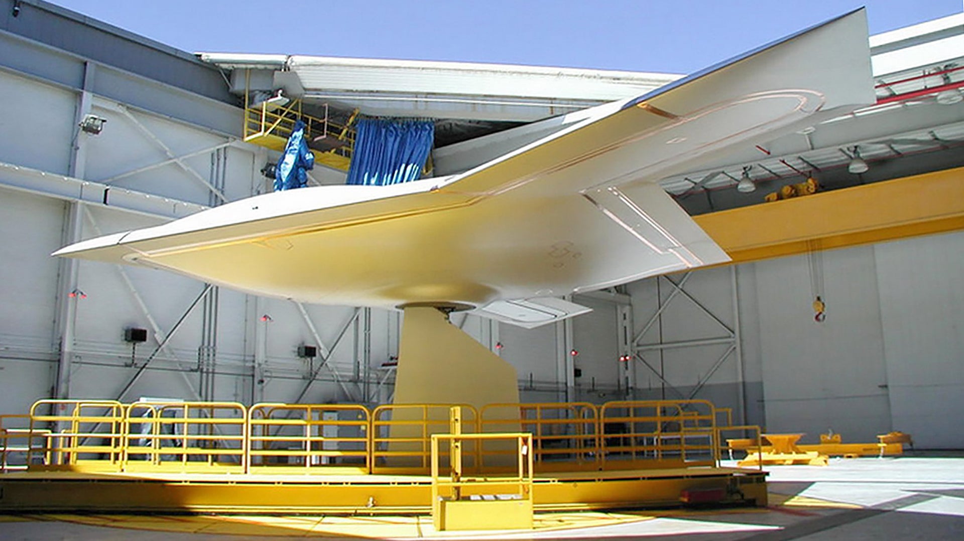
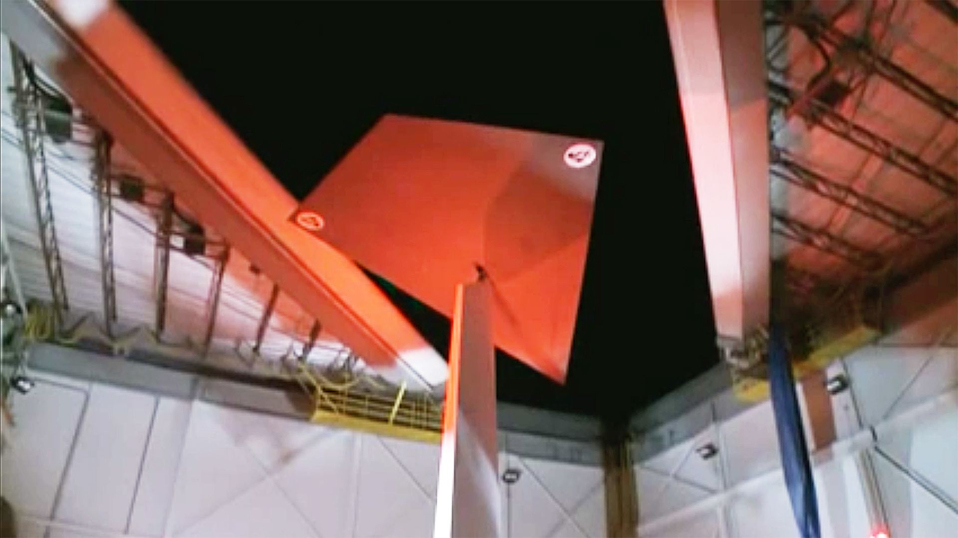
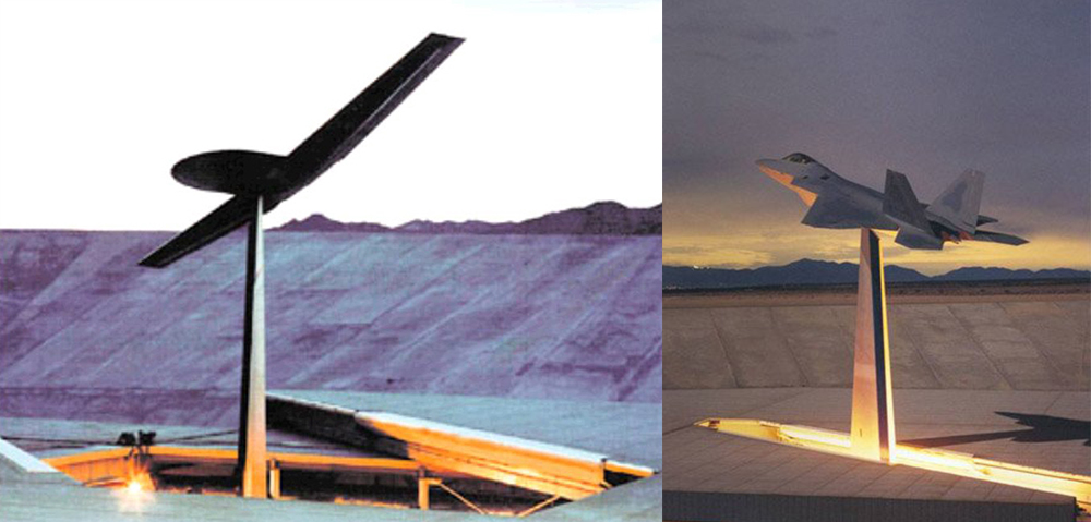
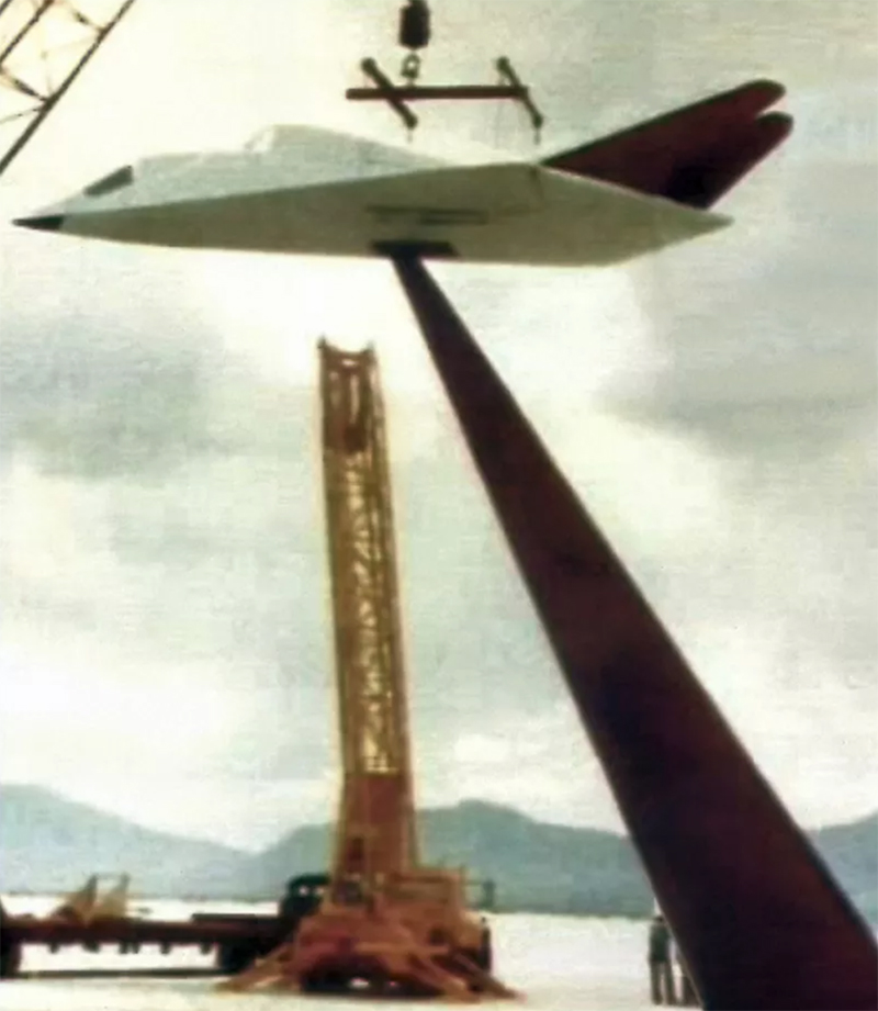
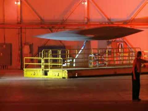
For testing, models (or even full sized aircraft) are brought into the Upper Chamber through the side sliding doors, raised by the bridge hoist, and placed over the tip of the pylon. After any necessary calibration, the roof of the Upper Chamber is opened and the pylon begins to rise. The pylon, which was upgraded in May, 1996 with a new, stealthier design (called a “Squareback Superskirt” by Lockheed), has the capability to move the model fore and aft 7′ or rotate it 360 degrees, to help clear the opening in the roof of the Upper Chamber. The movement capabilities of the pylon are also used in the testing program.
When the pylon reaches full extension, hydraulic cylinders tilt the pylon forward to an angle of 55 degrees from horizontal and the roof may close beneath it. When fully raised in its normal tilted position, it can place a model or actual aircraft (weighing up to 30,000 pounds with dimensions up to 105′ by 73′) about 100′ above the roof of the Upper Chamber.
The silvery stretched pumpkin seed shape on the end of the main pylon, (and the shape on the pylon at Pit 2), is a “polecap”. The “Star”, a company newspaper published by the Lockheed Martin Skunkworks, in the June 21, 1996 issue, ran a photo of the new pylon and polecap on its front page (shown below). The polecap is used during calibration of the main pylon. The shape of the pylon is so stealthy, that only the very tip of the pylon ends up being a significant source of signal return. To minimize this, a precisely shaped polecap is placed on the tip of the pylon to eliminate any radar returns from this spot. Then, once the very small return from the pylon is accurately determined and the system calibrated, the polecap is removed and a model put in its place. Perhaps surprisingly, the polecap was fabricated for Lockheed by a boat-building firm, Goetz Boats in Bristol, Rhode Island. It consists of aluminum honeycomb and carbon fiber, and the band along the outside edge is made of Kevlar, and the whole thing coated with RAM. After fabrication, it was shipped across country on a flatbed truck, looking to the world like the hull of a racing yacht.”
So a ton of engineering went into what appears as a fairly sparse but peculiar facility from a distance, and from above. The Pentagon contracted their own iteration of the design around the same time as Helendale was receiving its upgrades in 1985. Known as the Radar Advanced Measurements (RAM) and Radar Target Scatter (RASCAT) facility, it’s part of the National Radar Cross Section Test Facility (NRCSTF). The remote installation is located near Holloman AFB, among the White Sands Missile Range. It is the most advanced RCS range in the government’s portfolio and features a very similar underground staging facility as the one built at Helendale.
The main NRCSTF, located roughly 35 miles from the RAS/RASCAT facility, is where Northrop and Lockheed had their “pole off” during the XST competition, which ended in Lockheed winning the contract that would eventually give birth to Have Blue and the F-117 Nighthawk. During this early test of stealth design, the radar operator thought Lockheed’s “Hopeless Diamond” model fell off the pole until a bird landed on it and a return suddenly showed up on his scope.
You can get an unprecedented look side Lockheed’s Helendale RCS range in this video, which includes some very interesting comments from one of the top engineers that runs the site on what has been tested there, and what is possibly flying today under the cloak of deep classification:
With the big changes that have come to rapid prototyping and additive manufacturing, one would have to imagine that building new models and shapes to test at RCS ranges like Helendale has become a faster, cheaper affair for major aerospace companies like Lockheed Martin. It is known that the Skunk Works in particular has taken a very aggressive approach to these capabilities, along with efficiently building large composite structures, dating back to the early 2000s. And considering how potential enemies’ radar and integrated air defense system technology is rapidly evolving, being able to better validate and tune new designs to be as stealthy as possible has become more important than ever.
Whereas stealth aircraft like the F-117, and even the F-35 to a large degree, are optimized for low observability in certain radar bands and from certain aspects, next generation stealth aircraft designs, like the B-21 Raider, will feature broadband low observability, which aims to counter a wide number of frequency bands from all aspects. Even morphing aircraft structures will work to reduce an aircraft’s detectability by radar in the future. As such, testers at Helendale and other RCS facilities will be more challenged than ever to provide the critical data needed to keep stealth a relevant technology in the coming decades and to validate much more dynamic aircraft designs against multiple radar bandwidths.
But regardless of its capabilities or its critical mission, when it comes to just visuals alone, there are few facilities in the world that look as Hollywood ready as the Helendale RCS range.
Contact the author: Tyler@thedrive.com
Loading comments…
Comments couldn’t be loaded. Please refresh the page.